
Gm 4 Wire Alternator Wiring Diagram Wiring Diagram Database
The GM 4-wire alternator is a popular choice for many vehicles, so understanding the wiring diagram can help you understand how it works and how to make the necessary repairs. The four wires of the GM 4-wire alternator are the ground wire, the output wire, the sense wire, and the regulator wire. The ground wire is used to connect the alternator.

Understanding The Delco Chevy 4Wire Alternator Wiring Diagram Wiring Diagram
In the realm of automotive wonders, the 4-wire alternator wiring diagram holds a mystical allure. Like threads in an intricate tapestry, these wires dance together to breathe life into vehicles. Discovering their purpose, one can transcend the ordinary and uncover the secrets of automotive energy. Unleash your inner tech guru, and dive headfirst into the enigmatic world of alternator wiring.

Denso 4 Wire Alternator Wiring Diagram Collection
A 4 wire alternator wiring diagram typically consists of four basic elements: a battery, a starter, an alternator, and a voltage regulator. The battery receives power from the alternator which is then converted into usable electrical energy for the car's electrical system. The starter is responsible for providing the initial spark that starts.

4 Wire Alternator Wiring Diagram
An alternator wiring diagram will help you get the basic know-how of the circuit and how the components are linked together in a circuit. So, without further ado, let's dive in. Do you want to know more about what is alternator wiring diagram and how to make your own alternator wiring diagram?

Chevy 4 Wire Alternator Wiring Diagram
1. What Is An Alternator For? 2. How Does An Alternator Work? 3. Alternator Wire Overview 4. Wire Alternator Wiring Diagram: What Wires Go Where? 5. What Are The 4 Wires On An Alternator 6. What Are The 4 Terminals On An Alternator? 7. How To Wire An Alternator To Charge A Battery? 8. FAQs 9. Final Thoughts What Is An Alternator For?

4 Wire Alternator Wiring Diagram Wiring Diagram Schematic
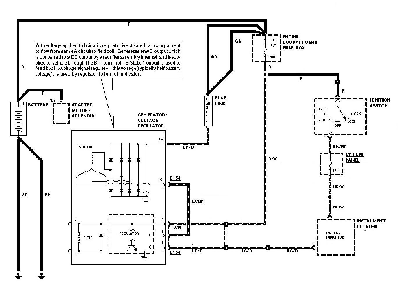
Alternator Voltage Regulation 101 (with Wiring Diagrams) - In The Garage with CarParts.com Learn how a car alternator works and find detailed alternator wiring diagrams, including for 3-wire connections in this article. Read on.
Gm 4 Wire Alternator Wiring Diagram Wiring Diagram Image
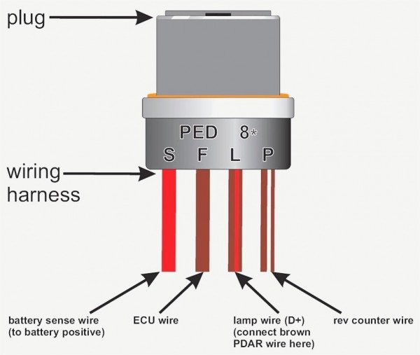
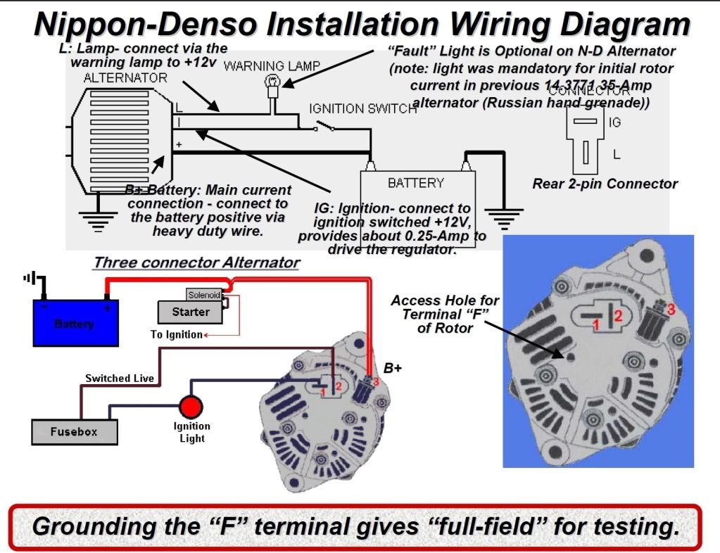
This diagram will help you connect the alternator correctly. The diagram includes four basic wires: the battery wire, the alternator wire, the ignition wire, and the ground wire.
Gm 4 Wire Alternator
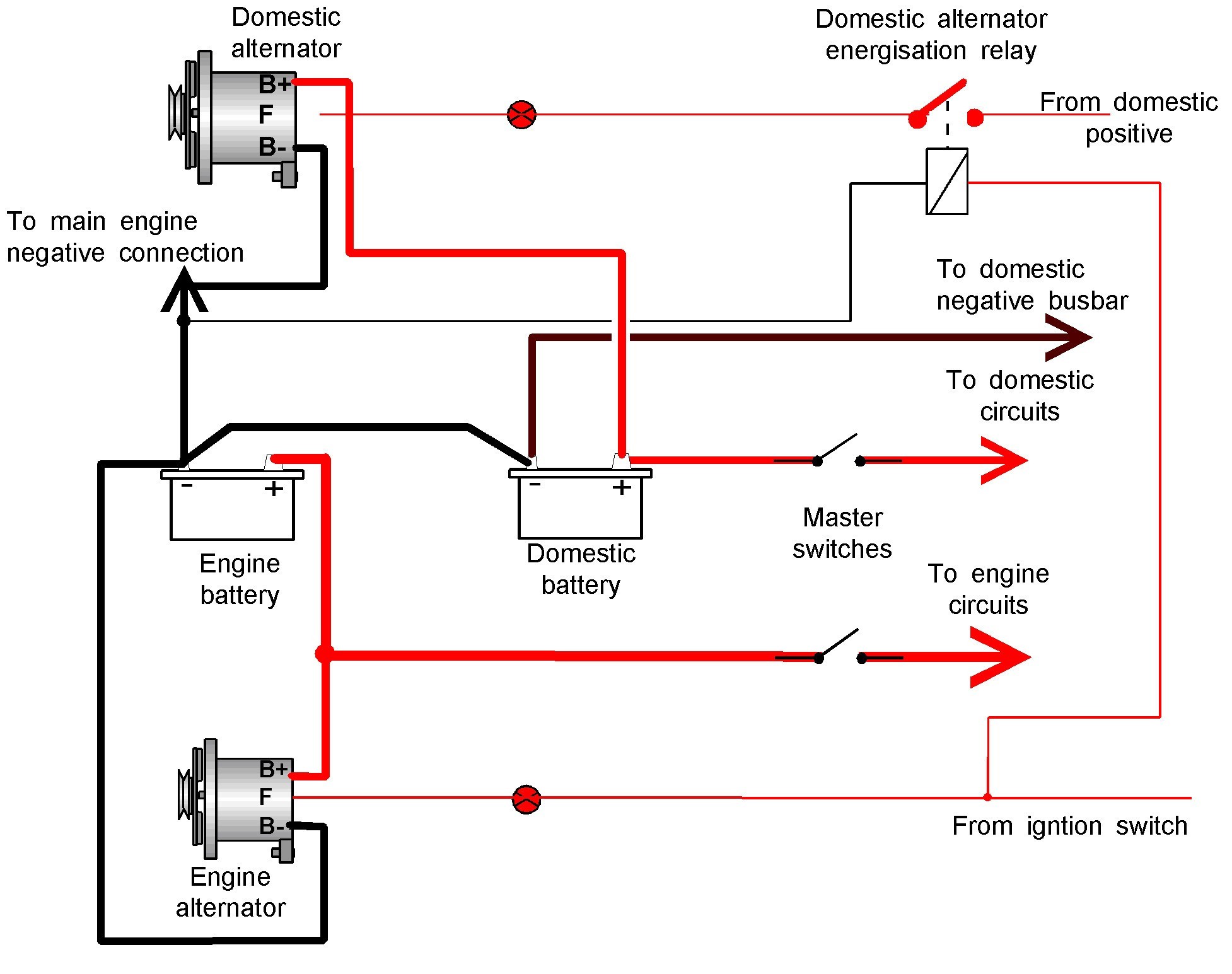
The alternator wiring diagram 4 wire consists of four main parts: battery, starter motor, alternator, and voltage regulator. Each of these components is connected to the alternator via two wires. The two wires that connect the battery to the alternator are called the positive and negative terminals.

Gm 4 Wire Alternator Wiring Diagram Easy Wiring
4 pin alternator wiring diagrams are essential for understanding how to connect and control the electrical system in a vehicle. These diagrams provide a visual representation of the wiring connections between the alternator, battery, and other components.
Gm 4 Wire Alternator Wiring Diagram Cadician's Blog
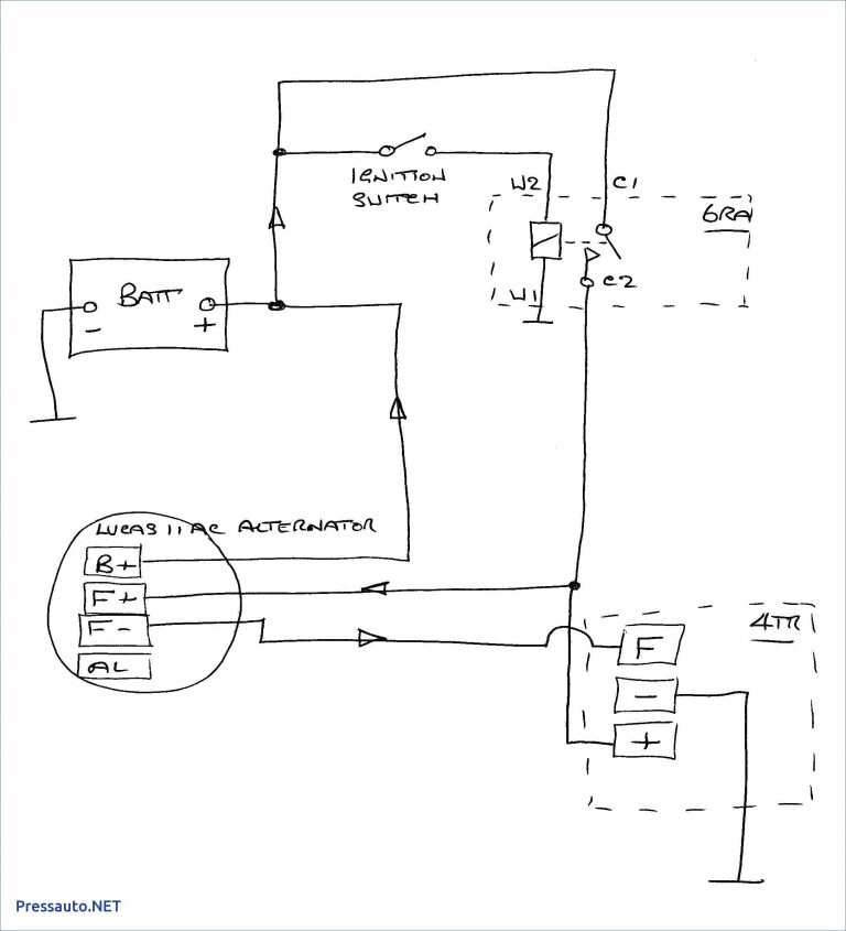
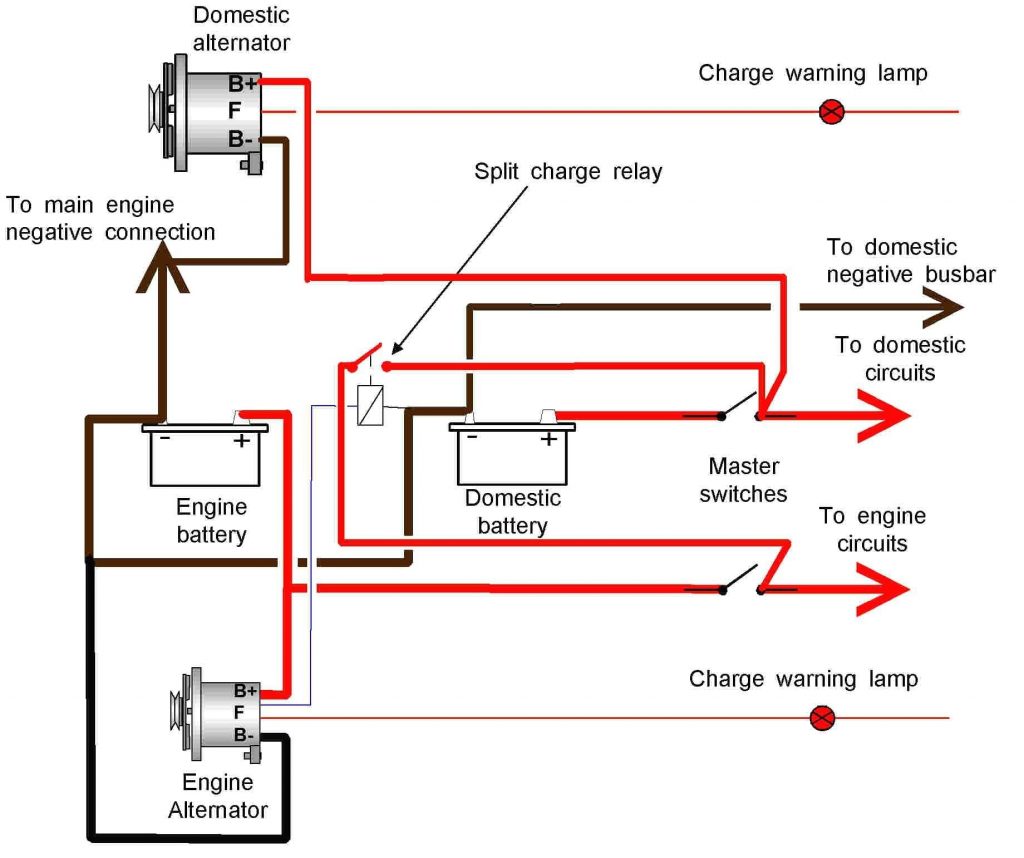
The first step is to identify the main components of the 4 Wire Alternator Wiring Diagram. Generally, the battery is connected to the alternator, while the alternator is connected to the engine. Next, you'll need to attach the alternator's field wire to the ignition switch, then connect the alternator's output wire to the battery.

Everything You Need To Know About Alternator Wiring Diagrams WIREGRAM
A 4 wire alternator wiring diagram is a simple visual representation of the connections between the alternator, the battery, the ignition switch, and the voltage regulator. The diagram can provide a step-by-step guide to connecting the different components.
4 Wire Alternator Wiring Wiring Diagrams Hubs Alternator Wiring Diagram Cadician's Blog
A 4 Pin Alternator Wiring Diagram is a diagram that shows the locations of the four pins that are used to connect the alternator to the car's electrical system. This diagram will help you understand exactly how the wiring works, allowing you to properly install the alternator and ensure it is working correctly.
Alternator Wiring Diagram 4 Wire
4 Wire Alternator Wiring Diagram is the linchpin of a vehicle's electrical system, seamlessly connecting components from the GM to Delco. It ensures an efficient conversion of alternating current from the alternator to direct current for your battery, harmonizing the electrical demands of any car, whether Ford or Chevrolet.

4 Wire Alternator Wiring Diagram Wiring Digital and Schematic
As the following wiring diagram illustrates, a 4-wire alternator allows you to convert mechanical energy into electrical energy, especially in motor vehicles. In the below wiring diagram, we have a battery connected to the 120A alternator that passes the current to the IC regulator.
Basic Wiring Diagram For Alternator
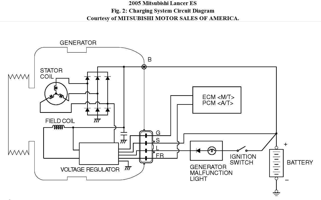
The 4 wire alternator wiring diagram will show how each wire should be connected to the correct terminal. It is important to use the correct type and size of wire for each connection to prevent any problems with the system. The black wire should be connected to the "B" terminal and the red wire should be connected to the "S" terminal.
4 Wire Alternator Wiring Diagram True Story
The Alternator Wiring Diagram 4 Wire is typically included in the car's owner manual and should be consulted when installing or repairing the system. Additionally, some manufacturers provide diagrams online or at their dealerships. Having this diagram available is especially helpful for those who are new to working on cars.
